
 |
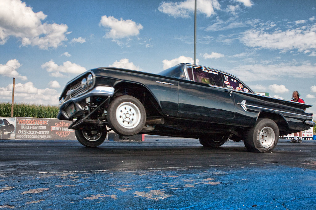
| ©Photo credit Mike Lippeth |
There Are Forces at Work You Can Possibly Imagine
When you break it down to its simplest level, any reciprocating machine generates vibration that is transmitted throughout the engine as a whole. This energy is absorbed by the engine mounts and frame while also creating torsional oscillations in the crank shaft and other shafting. These forces are generated by constantly changing accelerations of rotating and reciprocating mass and by the periodic forces imposed on components by the combustion process itself.
Now we start to hit the really dry stuff. Be sure you have a cup of coffee. Here is a lolcat to look at before you dig in. Please reference this figure if any of the below starts to sound boring or repetitive.
 |
| Image from icanhascheezburger.com |
To begin, imagine an upright single-cylinder engine (below.) As the piston travels up and down there must be upward and downward force acting upon it, reacted through the connecting rod and crank mains to the block. These forces are of equal magnitude and oppose each other. This up and down oscillation of the moving components creates a vibration along the vertical axis of the engine.
The crank arm and big end of the connecting rod sling back and forth in the lateral direction creating a horizontal imbalance, visible as a side-to-side vibration in the engine block itself. In the longitudinal direction, there are no inertia forces generated by the reciprocating components as this fore-to-aft axis is perpendicular to the plane of rotation.
 Since we have described the inertial forces in three perpendicular directions, the system can be described by a single vector equation, where the longitudinal component is zero. Remembering Newton’s First Law, F=ma, we can see that the force generated by this oscillation is proportional to the mass and acceleration of the rotating components.
The force generated by these rotating components must be balanced by a reaction force on the engine block, which will vibrate as a function of this force and its own mass. Thus, a block with fifty times the mass of the rotating components will experience two percent of the acceleration experienced by the rotating mass, while experiencing forces of the same magnitude.
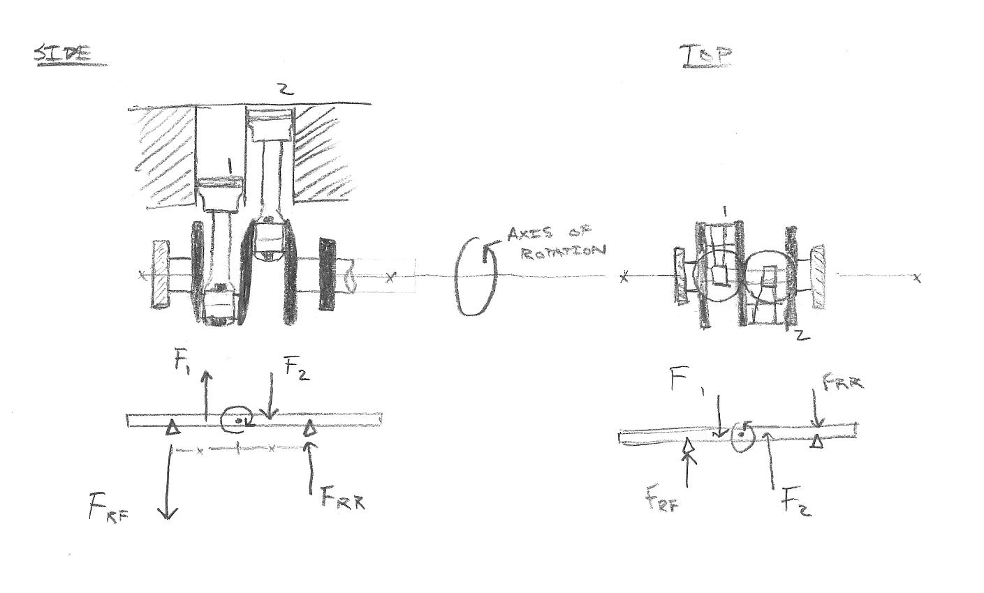
Inertial force alone can create not only a vertical and lateral vibration, but can create moments that tend to rock the engine as well. Consider my quickly-drawn two cylinder engine below.

While piston one is being pushed upward, it creates a downward force on the crankshaft illustrated in the Free Body Diagram (FBD) below it. At the same time, piston two is being pulled down. This force couple is balanced, so there is no net acceleration, but there is an oscillating moment generated about (and within) the crank, which must be balanced by the engine block and manifests visibly as a rocking motion about the lateral axis (side view.)
Similarly, the lateral motion of the big end of the rod and the crank pins create an oscillating force pair that creates a changing moment in the crank. From the outside of the engine, this is seen as a rocking about the engine’s vertical axis. While moments about these axes are generated by force couples, rocking motion about the crankshaft axis occurs even in a single-cylinder engine as an alternating inertia torque generated by varying piston acceleration.
If the engine is mounted rigidly to a frame (which can create concerns especially with fatigue failure) the reactive force is accommodated by the frame. Conversely, the engine can be mounted on a material that allows the engine to move, (or floating in space, for that matter.) In this case, the force created by the rotating mass is balanced by an acceleration of the engine block itself (called floating power.) In reality, stiffness of these mounts is dictated by packaging constraints, overall forces the mounts must handle, allowable compliance/movement and NVH considerations, which I will exemplify later.
The next thing to consider is the effect of combustion on the mass of the engine. As discussed in my Rotation, Rotation, Rotation post, the pressure of combustion creates a downward force on the piston, which is reacted by the connecting rod at some angle to the crankshaft and thus engine block (Q). The rod is a two-force member and induces some lateral force on the piston thrust face (S, where S = F tanø) which is also balanced by the crank mains (a force couple, just like Q) Thus, the compression force in the connecting rod is greater than the force acting on the piston alone when ø is non-zero (Q=F/cosø, where cosø is always <=1).The friction force also creates a rocking moment of the piston in the bore, which accelerates wear especially in short-skirt piston designs.
The net result of this combustion force on the engine as a whole is only a single output torque (Qx) – all lateral and horizontal forces are balanced within the system, but the rotational torque about the crankshaft is not balanced, resulting in a net torque acting on the engine as a whole. This torque is what spins wheels and twists frames.
In order to reduce the magnitudes of all the inertial forces at work we can balance the engine. This balance begins with the design of the crankshaft. By adding counterweights opposite the crank pins, these lateral and vertical inertial forces and moments can at least in part be balanced. There are far better illustrations than I could make of how to draw vector diagrams describing these forces and moments, specifically in the text Mechanical Vibrations by J. P. Den Hartog, which has served as my primary reference in this post. Also relevant for engine theory is Advanced Engine Technology by Heisler, which I have inadvertently “donated” to OU’s FSAE team at some point. What it boils down to however is that some engine configurations are more balanced than others, due to the reciprocating motion of multiple pistons.
For example, a four-cylinder flat-plane four-stroke engine (say that five times fast!) has balanced primary forces and moments, while secondary forces and moments are unbalanced. An inline-six has all forces and moments balanced – Inline 6’s are known for their smooth operation and longevity. BMW, Rolls Royce, Jaguar, and other luxury marques have used inline 6’s to great success because they develop excellent torque and power very smoothly, befitting a luxury brand. Inline 8’s are also completely balanced, and have no odd-order driveline harmonics present in inline 6’s due to an even number of power strokes.
This brings up an important consideration about fatigue. Given that the forces acting on the crankshaft are high and cyclic in nature, increasing the length of the crankshaft also increases the magnitude of the induced moments, and while they are balanced, they still exist as an internal moment within the crankshaft. It applies to torsional moments as well. While some of the vibrations that twist the crankshaft can be mitigated by use of an elastomer-bonded weight or fluid filled harmonic damper, by lengthening the crankshaft it suffers more angular deformation, which in long inline engines typically manifests as fatigue cracking near the rear main bearing journal, since the driving torque from combustion is reacted through the rear of the crankshaft to the wheels. This raises practical issues on reliability and longevity. These considerations contribute to the widespread adoption of the V8 in the 1950’s.
So far I haven’t mentioned much about boxer engines or balance shaft engines, but for the sake of brevity I will mention them quickly. Some engines utilize balance shafts, which are geared to the crankshaft and allow for additional inertial balancing without increasing the mass of the crankshaft itself. This can aid in packaging in some cases, and balance shafts are used in many engines successfully. Boxer engines (horizontally opposed) typically have favorable balance characteristics due to the opposed nature of the pistons, but generate rocking moments about the vertical axis. They also take up a lot of space and often duplicate components like cylinder heads, camshafts, and gearing compared to inline versions with the same number of cylinders.
So Now You Have To Build It
These topics are important when designing connecting rods and considering tolerances and oil pressure specifications in order to prevent part breakage and minimize wear. Every design parameter is of critical importance. It is an engineering challenge to reduce weight, maintain acceptable geometry, and still maintain a sufficient torsional strength, whether through the marvel of Finite Element Analysis or simple hand calculations.
Designing proper counterweights or balance shafts can be done with hand calculations, but in another fantastic deus ex machina, the computer comes to the rescue with solid modeling programs that can effectively predict mass and inertial properties before a component is ever manufactured, reducing testing and redesigning. This also allows designers to consider resonant modes in the crankshaft as illustrated below.
This applies to car frames as well. All of the net forces and moments generated by an engine must be reacted by the frame of the vehicle. Achieving satisfactory torsional rigidity is much easier with computer simulation and FEA, but as illustrated by the headline graphic, addition of gross amounts of horsepower to a frame that was wet-noodle rigid from the factory can lead to entertainingly and crowd-pleasingly large amounts of frame flex, but cause performance and durability to suffer. It is necessary to design any vehicle whether OEM or race-spec to fulfill design intents and goals.
For the hobbyist, choosing rods, pistons, and crankshafts is typically less involved. There are aftermarket offerings and OEM offerings; custom designed crankshafts, pistons are typically in the realm of professionally sponsored racing vehicles. When it comes to assembling your hot rod, you don’t always need the fanciest billet components, and stock components can be often be reused, inspected, or modified to achieve horsepower and reliability goals. There is also something to be said for reuse of seasoned components – they have proved they are free from blatant material defect and as long as they are still in spec, they are perfectly good to use again.
Balancing is another matter. The engine designer decides how the engine will be balanced. The crankshaft counterweights in a typical American V8 are near the proper amount to achieve balance. Variations in components’ masses may necessitate a small change in the counterweight mass. To achieve this, all pistons and rods are milled to reduce the mass of every component to that of the lightest respective component. The crankshaft is then dynamically balanced on a machine with the flywheel and harmonic dampener (which themselves contain counterweights,) and all counterweights are successively milled until a good balance is achieved. This is called external balance.
Because they are not designed as internally balanced engines, an American V8 can retrofitted using heavy metals embedded in the crankshaft counterweights. This replaces the additional balance mass typically provided by the flywheel and harmonic dampener counterweights. By moving this mass from the end of the crankshaft to a position closer to the revolving and reciprocating mass, internal stresses in the crankshaft and rocking moments are reduced and the engine runs more smoothly overall. However, this is expensive and requires a lot of machine work to retrofit, so it is typically reserved for race engines.
The inertial torque it requires to angularly accelerate the rotating assembly is a function of mass. Thusly, decreasing the mass of all rotating components not only reduces the magnitude of the inertial forces generated within them, but also reduces the rotational moment of inertia and the inertial torque required for angular acceleration of the components. This effect is the reason crankshaft lightening, aluminum/CFRP driveshafts and aluminum flywheels are present on high-end or race-modified cars. The lower the rotational moment of inertia of any driven component, the more torque gets to the wheels. Again I’m going to go on about tradeoffs – you wouldn’t design a part so light it breaks, and more mass in the rotating assembly smoothes power delivery and reduces vibration.
The vibration reacted to the frame can be severe. When we switched from a Honda F4i four-cylinder to an Aprilia V-twin, the unbalanced primary forces of the Aprilia coupled with the larger variations in torque output created incredible vibrations. We attempted to mitigate this for the sake of driver comfort with rubber bushings, but even with the stiffest rubber the mount flexed enough for chain tension to slacken, which added chain chatter to the destructive forces.
In fact, even after switching to aluminum bushings (much to the driver's spine's dismay,) the torque loading of the engine was sufficient to plastically deform the engine mounts, reducing chain tension and causing a nasty torque pulsation. This design failure on our part was due to a gross underestimation of the shock loading of driveline components and poor load path considerations when designing the engine mount - a more thorough investigation would have kept our tube frame from deforming to the point where it required cutting and welding additional tubes to support the motor. If we had focused on systems engineering and not designed the frame simply for torsional rigidity, this issue would have never occurred.
We slapped a video camera on to observe deflection. Note the marks on the header tube where the diff previously impacted.
Every component can be optimized in some fashion and in any case design work is a compromise, from how much money you want to pay the engineer to reduce piston mass to what alloy is sufficiently strong and cheap for your crankshaft, the list goes on and on. There are volumes written about project management and goal-setting. This is something that programs like FSAE are terrific at teaching, you have to not only design a race car, but find the money to pay for it, set goals and deadlines to be met, and sacrifice the three grams of weight you could have saved in order to assemble your car with time for testing.

Vibration is one of the most destructive forces to machinery (other than Vin Diesel,) leading to fatigue failures with less-than-obvious causes. While this post is only written on the most general level, it should serve as a springboard to more in-depth investigation, and just in writing it I have learned a lot more than when I started.
References and Interesting links:
http://www.autozine.org/technical_school/engine/smooth1.htm
http://www.codecogs.com/reference/engineering/machines/balancing_of_inertia_forces.php
Bosch Automotive Handbook by Robert Bosch
Advanced Engine Technology by Heinz Heisler
Mechanical Vibrations by J. P. Den Hartog

The force generated by these rotating components must be balanced by a reaction force on the engine block, which will vibrate as a function of this force and its own mass. Thus, a block with fifty times the mass of the rotating components will experience two percent of the acceleration experienced by the rotating mass, while experiencing forces of the same magnitude.
Inertial force alone can create not only a vertical and lateral vibration, but can create moments that tend to rock the engine as well. Consider my quickly-drawn two cylinder engine below.
While piston one is being pushed upward, it creates a downward force on the crankshaft illustrated in the Free Body Diagram (FBD) below it. At the same time, piston two is being pulled down. This force couple is balanced, so there is no net acceleration, but there is an oscillating moment generated about (and within) the crank, which must be balanced by the engine block and manifests visibly as a rocking motion about the lateral axis (side view.)
Similarly, the lateral motion of the big end of the rod and the crank pins create an oscillating force pair that creates a changing moment in the crank. From the outside of the engine, this is seen as a rocking about the engine’s vertical axis. While moments about these axes are generated by force couples, rocking motion about the crankshaft axis occurs even in a single-cylinder engine as an alternating inertia torque generated by varying piston acceleration.
If the engine is mounted rigidly to a frame (which can create concerns especially with fatigue failure) the reactive force is accommodated by the frame. Conversely, the engine can be mounted on a material that allows the engine to move, (or floating in space, for that matter.) In this case, the force created by the rotating mass is balanced by an acceleration of the engine block itself (called floating power.) In reality, stiffness of these mounts is dictated by packaging constraints, overall forces the mounts must handle, allowable compliance/movement and NVH considerations, which I will exemplify later.
 | |
| Force diagram of a typical piston-rod-crank assembly |
The next thing to consider is the effect of combustion on the mass of the engine. As discussed in my Rotation, Rotation, Rotation post, the pressure of combustion creates a downward force on the piston, which is reacted by the connecting rod at some angle to the crankshaft and thus engine block (Q). The rod is a two-force member and induces some lateral force on the piston thrust face (S, where S = F tanø) which is also balanced by the crank mains (a force couple, just like Q) Thus, the compression force in the connecting rod is greater than the force acting on the piston alone when ø is non-zero (Q=F/cosø, where cosø is always <=1).The friction force also creates a rocking moment of the piston in the bore, which accelerates wear especially in short-skirt piston designs.
The net result of this combustion force on the engine as a whole is only a single output torque (Qx) – all lateral and horizontal forces are balanced within the system, but the rotational torque about the crankshaft is not balanced, resulting in a net torque acting on the engine as a whole. This torque is what spins wheels and twists frames.
In order to reduce the magnitudes of all the inertial forces at work we can balance the engine. This balance begins with the design of the crankshaft. By adding counterweights opposite the crank pins, these lateral and vertical inertial forces and moments can at least in part be balanced. There are far better illustrations than I could make of how to draw vector diagrams describing these forces and moments, specifically in the text Mechanical Vibrations by J. P. Den Hartog, which has served as my primary reference in this post. Also relevant for engine theory is Advanced Engine Technology by Heisler, which I have inadvertently “donated” to OU’s FSAE team at some point. What it boils down to however is that some engine configurations are more balanced than others, due to the reciprocating motion of multiple pistons.
For example, a four-cylinder flat-plane four-stroke engine (say that five times fast!) has balanced primary forces and moments, while secondary forces and moments are unbalanced. An inline-six has all forces and moments balanced – Inline 6’s are known for their smooth operation and longevity. BMW, Rolls Royce, Jaguar, and other luxury marques have used inline 6’s to great success because they develop excellent torque and power very smoothly, befitting a luxury brand. Inline 8’s are also completely balanced, and have no odd-order driveline harmonics present in inline 6’s due to an even number of power strokes.
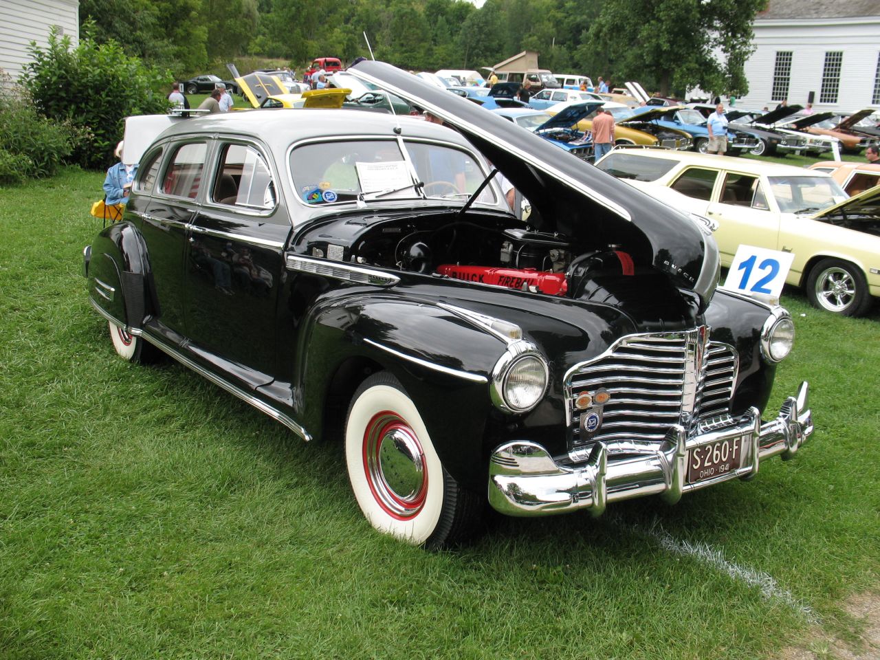 |
| The Buick Fireball 8 was an inline 8 configuration engine produced from 1931 to 1953. It utilized overhead valves and ranged from 221 to 345 cubic inches, carrying a maximum power rating of 189hp @ 3800 RPM in 1952, but was subsequently replaced by Buick’s more powerful and more robust Nailhead V8. ©Photo credit Cris Brown. |
This brings up an important consideration about fatigue. Given that the forces acting on the crankshaft are high and cyclic in nature, increasing the length of the crankshaft also increases the magnitude of the induced moments, and while they are balanced, they still exist as an internal moment within the crankshaft. It applies to torsional moments as well. While some of the vibrations that twist the crankshaft can be mitigated by use of an elastomer-bonded weight or fluid filled harmonic damper, by lengthening the crankshaft it suffers more angular deformation, which in long inline engines typically manifests as fatigue cracking near the rear main bearing journal, since the driving torque from combustion is reacted through the rear of the crankshaft to the wheels. This raises practical issues on reliability and longevity. These considerations contribute to the widespread adoption of the V8 in the 1950’s.
So far I haven’t mentioned much about boxer engines or balance shaft engines, but for the sake of brevity I will mention them quickly. Some engines utilize balance shafts, which are geared to the crankshaft and allow for additional inertial balancing without increasing the mass of the crankshaft itself. This can aid in packaging in some cases, and balance shafts are used in many engines successfully. Boxer engines (horizontally opposed) typically have favorable balance characteristics due to the opposed nature of the pistons, but generate rocking moments about the vertical axis. They also take up a lot of space and often duplicate components like cylinder heads, camshafts, and gearing compared to inline versions with the same number of cylinders.
So Now You Have To Build It
These topics are important when designing connecting rods and considering tolerances and oil pressure specifications in order to prevent part breakage and minimize wear. Every design parameter is of critical importance. It is an engineering challenge to reduce weight, maintain acceptable geometry, and still maintain a sufficient torsional strength, whether through the marvel of Finite Element Analysis or simple hand calculations.
Designing proper counterweights or balance shafts can be done with hand calculations, but in another fantastic deus ex machina, the computer comes to the rescue with solid modeling programs that can effectively predict mass and inertial properties before a component is ever manufactured, reducing testing and redesigning. This also allows designers to consider resonant modes in the crankshaft as illustrated below.
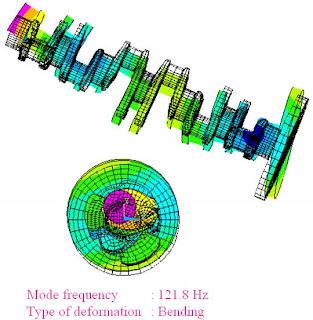 |
| For some more interesting pictures see the Abaqus blog. |
This applies to car frames as well. All of the net forces and moments generated by an engine must be reacted by the frame of the vehicle. Achieving satisfactory torsional rigidity is much easier with computer simulation and FEA, but as illustrated by the headline graphic, addition of gross amounts of horsepower to a frame that was wet-noodle rigid from the factory can lead to entertainingly and crowd-pleasingly large amounts of frame flex, but cause performance and durability to suffer. It is necessary to design any vehicle whether OEM or race-spec to fulfill design intents and goals.
For the hobbyist, choosing rods, pistons, and crankshafts is typically less involved. There are aftermarket offerings and OEM offerings; custom designed crankshafts, pistons are typically in the realm of professionally sponsored racing vehicles. When it comes to assembling your hot rod, you don’t always need the fanciest billet components, and stock components can be often be reused, inspected, or modified to achieve horsepower and reliability goals. There is also something to be said for reuse of seasoned components – they have proved they are free from blatant material defect and as long as they are still in spec, they are perfectly good to use again.
 |
| Some, however, are not reusable. |
Balancing is another matter. The engine designer decides how the engine will be balanced. The crankshaft counterweights in a typical American V8 are near the proper amount to achieve balance. Variations in components’ masses may necessitate a small change in the counterweight mass. To achieve this, all pistons and rods are milled to reduce the mass of every component to that of the lightest respective component. The crankshaft is then dynamically balanced on a machine with the flywheel and harmonic dampener (which themselves contain counterweights,) and all counterweights are successively milled until a good balance is achieved. This is called external balance.
Because they are not designed as internally balanced engines, an American V8 can retrofitted using heavy metals embedded in the crankshaft counterweights. This replaces the additional balance mass typically provided by the flywheel and harmonic dampener counterweights. By moving this mass from the end of the crankshaft to a position closer to the revolving and reciprocating mass, internal stresses in the crankshaft and rocking moments are reduced and the engine runs more smoothly overall. However, this is expensive and requires a lot of machine work to retrofit, so it is typically reserved for race engines.
The inertial torque it requires to angularly accelerate the rotating assembly is a function of mass. Thusly, decreasing the mass of all rotating components not only reduces the magnitude of the inertial forces generated within them, but also reduces the rotational moment of inertia and the inertial torque required for angular acceleration of the components. This effect is the reason crankshaft lightening, aluminum/CFRP driveshafts and aluminum flywheels are present on high-end or race-modified cars. The lower the rotational moment of inertia of any driven component, the more torque gets to the wheels. Again I’m going to go on about tradeoffs – you wouldn’t design a part so light it breaks, and more mass in the rotating assembly smoothes power delivery and reduces vibration.
The vibration reacted to the frame can be severe. When we switched from a Honda F4i four-cylinder to an Aprilia V-twin, the unbalanced primary forces of the Aprilia coupled with the larger variations in torque output created incredible vibrations. We attempted to mitigate this for the sake of driver comfort with rubber bushings, but even with the stiffest rubber the mount flexed enough for chain tension to slacken, which added chain chatter to the destructive forces.
In fact, even after switching to aluminum bushings (much to the driver's spine's dismay,) the torque loading of the engine was sufficient to plastically deform the engine mounts, reducing chain tension and causing a nasty torque pulsation. This design failure on our part was due to a gross underestimation of the shock loading of driveline components and poor load path considerations when designing the engine mount - a more thorough investigation would have kept our tube frame from deforming to the point where it required cutting and welding additional tubes to support the motor. If we had focused on systems engineering and not designed the frame simply for torsional rigidity, this issue would have never occurred.
We slapped a video camera on to observe deflection. Note the marks on the header tube where the diff previously impacted.
Every component can be optimized in some fashion and in any case design work is a compromise, from how much money you want to pay the engineer to reduce piston mass to what alloy is sufficiently strong and cheap for your crankshaft, the list goes on and on. There are volumes written about project management and goal-setting. This is something that programs like FSAE are terrific at teaching, you have to not only design a race car, but find the money to pay for it, set goals and deadlines to be met, and sacrifice the three grams of weight you could have saved in order to assemble your car with time for testing.

Vibration is one of the most destructive forces to machinery (other than Vin Diesel,) leading to fatigue failures with less-than-obvious causes. While this post is only written on the most general level, it should serve as a springboard to more in-depth investigation, and just in writing it I have learned a lot more than when I started.
References and Interesting links:
http://www.autozine.org/technical_school/engine/smooth1.htm
http://www.codecogs.com/reference/engineering/machines/balancing_of_inertia_forces.php
Bosch Automotive Handbook by Robert Bosch
Advanced Engine Technology by Heinz Heisler
Mechanical Vibrations by J. P. Den Hartog
No comments:
Post a Comment